- Products / Store
- >
- CubeSat Kit™ Modules
- >
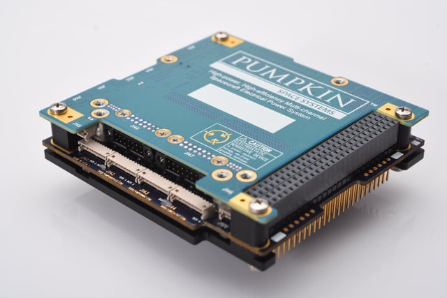
- High-power Multi-channel Electrical Power System Module (EPSM1)
High-power Multi-channel Electrical Power System Module (EPSM1)
Flight Hardware | Flight Qualified | Space Proven
The EPSM 1 serves as the nexus of a complete, high-performance and highly efficient FPGA-driven, GaNFET-based multichannel power system for small satellites. Its advanced functionality takes the guesswork out of managing high and varying power levels in small satellites.
The EPSM 1's power-handling circuitry is comprised of twelve non-isolated 250kHz switching blocks divided into three groups under FPGA and MCU control:
- The solar array inputs (SAI1 - SAI6)
- The batteries (BAT1 & BAT2)
- The outputs (3V3, 5V0, 12V & 28V)
The six SAIs blocks collect power for the outputs and for battery charging as required. Each SAI block independently implements a kHz-speed perturb-and-observe MPPT algorithm, with programmable maximum current setpoints and with automatic power equalization across all six SAIs. The SAIs blocks can handle up to 480W total solar input power.
Each independent battery block provides reserve power (up to 112W per battery) when the output loads exceed the total SAI input power. The EPSM 1 charges each connected 16.8V Li-Ion battery in CC/CV modes at up to 6A, with automatic CHG/DSG switchover. The recommended battery is Pumpkin's BM 2 4S2P battery module (not included), and the EPSM 1 is compatible with the BM 2's battery balancing, heaters, and all telecommands and telemetry.
Each output block provides a regulated output voltage at up to 5A (3V3 & 5V0) and 8A (12V & 28V), for a total of ~300W. Each output block has a programmable current limit, and the 28V block is switchable and can operate at lower voltages.
A Pumpkin SupMCU™ handles telecommands and telemetry via SCPI over I2C, and implements a variety of sophisticated additional features including a programmable WDT, programmable overtemperature limits OT1 & OT2, smart RBF and separation inhibits, automatic recovery from power deficit conditions and automatic recovery from solar panel shading. All telemetry is timestamped and fully formatted in engineering units; there is no need to apply calibration constants or conversion factors to EPSM 1 telemetry.
The EPSM 1 is provided with an integrated heat spreader and a built-in overvoltage clamp, and operates within substantially derated operating conditions. Three internal and eight external temperature sensors ports are also provided. The FPGA is SEU immune, and multiple EPSM 1s can be paralleled together. Per-block efficiency is typically > 99% at moderate-to-high currents.
-
Information
-
Compatibility
-
CAD
-
Documents
-
Restrictions
- EPSM1 module with one of three H1/H2 connector options (none, stackthrough or non-stackthrough)
- One Development Board 2, with EPSM1 installed on it
- One 710-02407 Load Board B
- Four 530-02435 12" / 300mm 10-conductor SAI harnesses to connect the EPSM1 to Load Board B
- One 530-02966 12" / 300mm 2-conductor RBF inhibit harness with flying leads
- One 530-02967 12" / 300mm 2-conductor Separation inhibit harness with flying leads
- One 710-01001 USB Debug Adapter (installed on Development Board 2) w/flex cable and USB cable
- Downloadable Windows-based GUI for firmware updates
- Downloadable Python-based GUI for SCPI-based command and telemetry development (requires a Total Phase™ Aardvark I2C/SPI Host Adapter -- not included)
The Pumpkin USB Debug Adapter provides a debugging terminal / command line interface (CLI) to the EPSM1. The dedicated Windows GUI is required for firmware updates, and connects to the EPSM1 via the USB Debug Adapter.
Does not include:
- Batteries
- Solar panels
- External power sources
- Flying-lead battery harnesses (can be ordered separately)
- All CubeSat architectures that employ the 104-pin connector, as well as others that can connect to the EPSM 1 directly
- Solar cell strings of maximum 28V and 2A (SAI1-SAI4) & 4A (SAI5 & SAI6)
- 16.8V batteries that can be charged using a CC/CV type charging scheme
- SUPERNOVA Remote GSIM (not included)
WARNING: The voltages and currents present on the S0-S5 and VBATT terminals of the H2 connector may result in damage or destruction of the EPSM 1 or of other connected modules if connected to systems that expect other voltages and/or currents at these terminals. Review the EPSM 1 datasheet and confer with Pumpkin before use.
Electrical Power System Module 1 (EPSM1) |
|
EPSM 1 Datasheet
|
|


