|
When FLEET Space had a last-minute opportunity to launch 3U worth of CubeSats on a Rocket Lab Electron launch vehicle, with the caveat that the CubeSats had to be ready in two weeks (!), they came to Pumpkin. We not only typically have nanosatellite-class equipment in stock, but we also have a proven track record of working quickly on projects that require outside-of-the-box thinking. Within two weeks, we needed to come up with a working architecture, source the required components / assemblies, make any modifications required, integrate the FLEET payload and antennas (the pixelated portion above), and provide a software framework upon which FLEET could write their mission software.
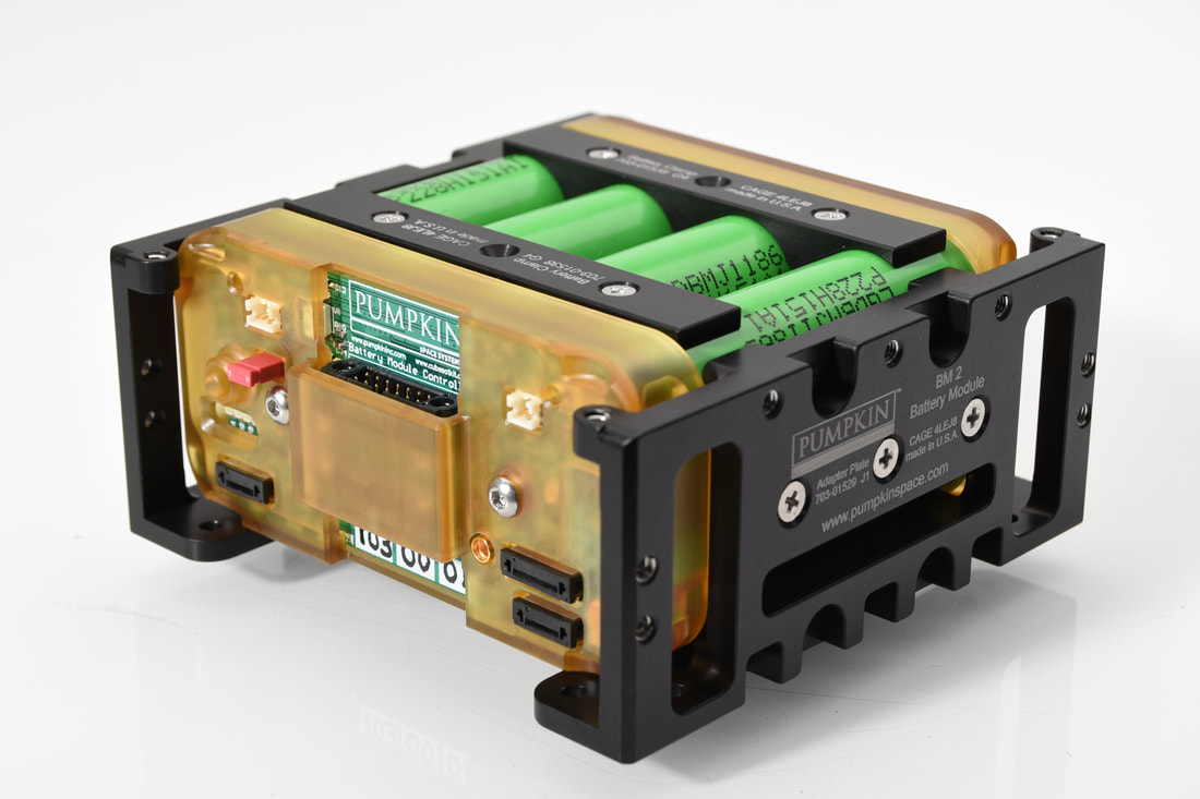
Given the very short notice and the desire to maximize the utility of the 3U of volume available on this ride, Pumpkin and FLEET settled on a dual-1.5U mission, with two hardware-identical 1.5U CubeSats. We decided to go with a battery-power-only architecture, as that reduced costs and complexity, and fits within the 1.5U available. Pumpkin immediately embarked on creating a new operating mode for our BM 2 battery; within a few days we had this up and running, and Proxima I/II were thus enabled. The two satellite were built with US and Australian teams working together and remotely, then environmentally tested with no issues, and finally delivered to Rocket Lab for LV integration. Proxima's Pumpkin components included:
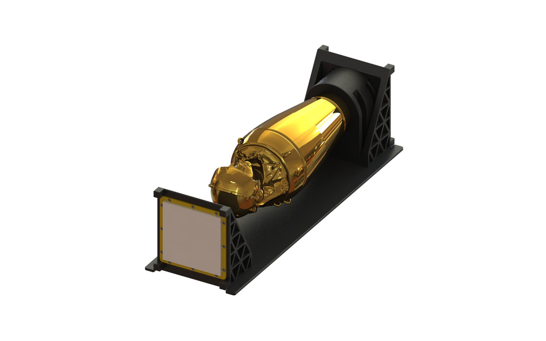
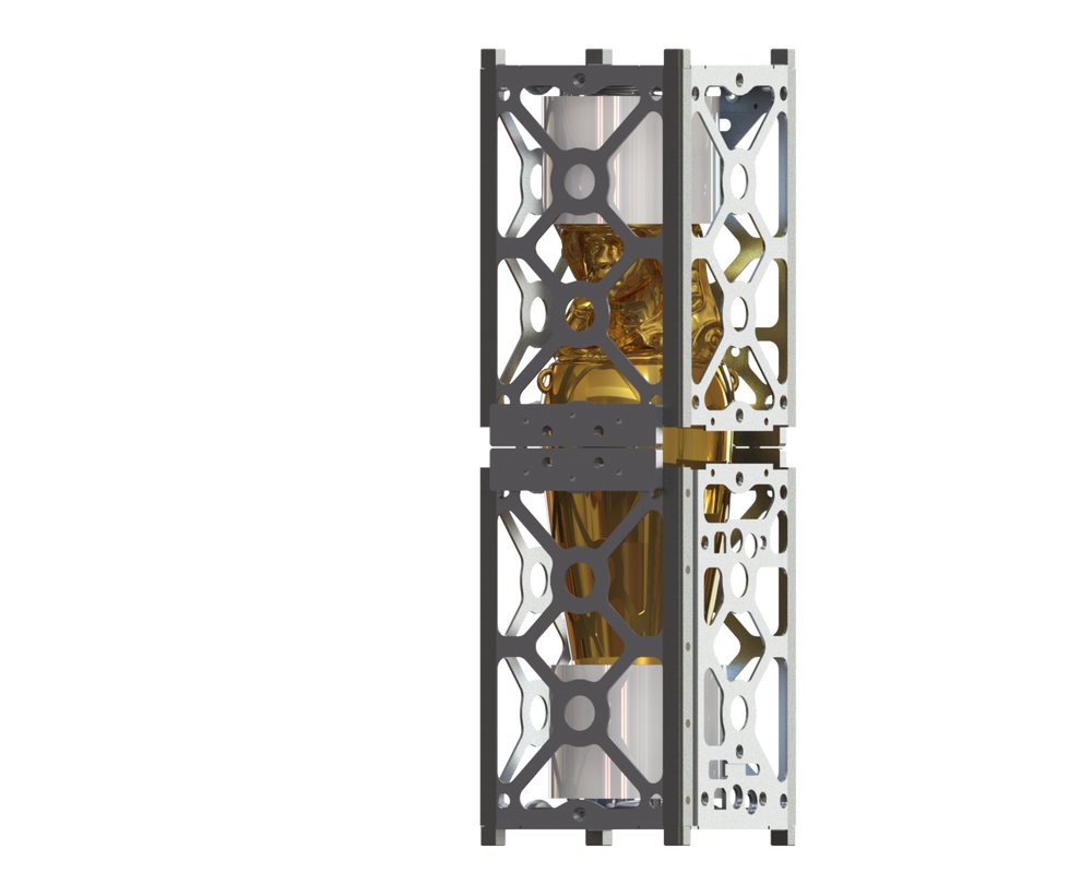
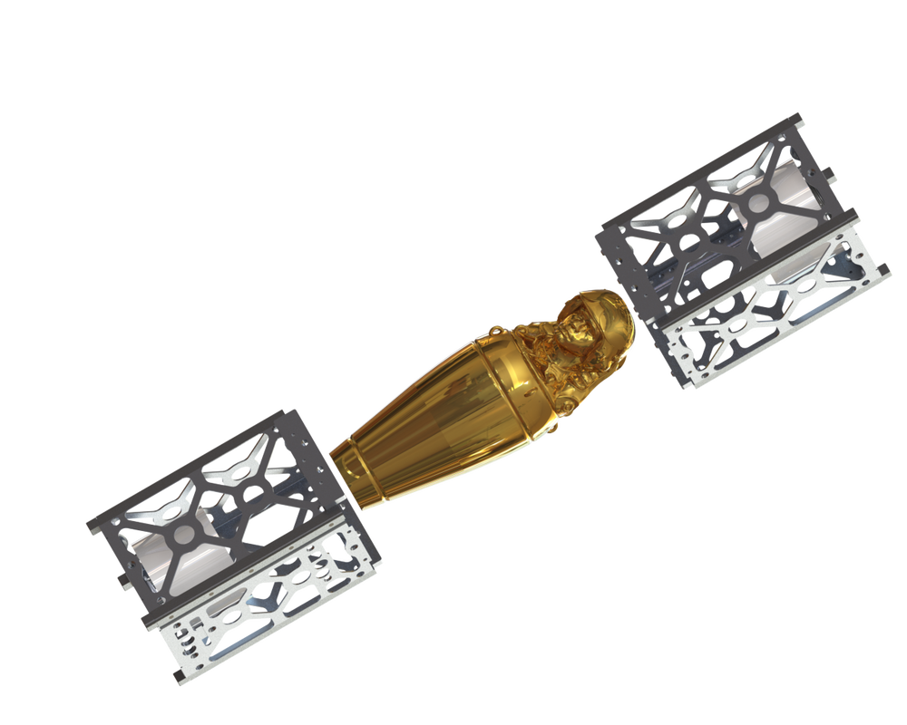
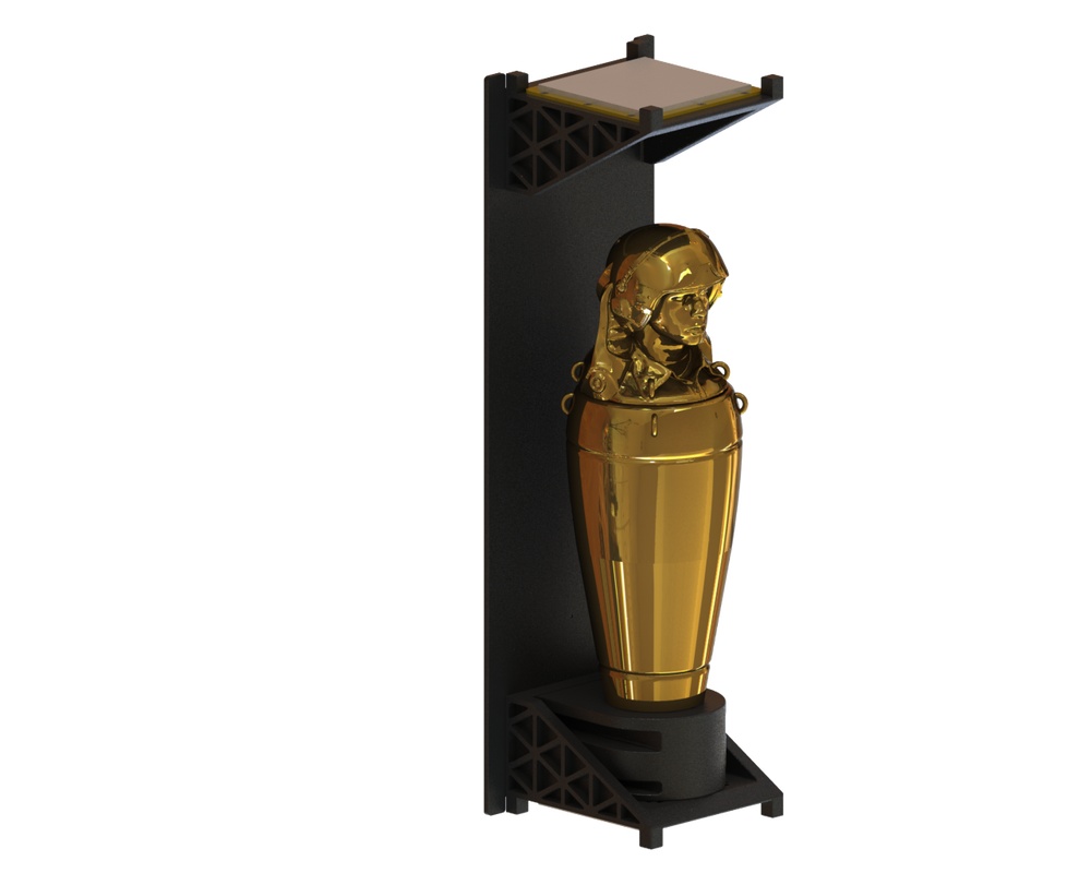
The Pumpkin bus components occupy around half the volume and mass of each Proxima CubeSat; FLEET's payload(s) occupy the rest. The GPSRM along with its power-efficient orbit propagator enable Proxima's mission ops, and the low-power 16-bit PPM E3 PIC24 MCU running Salvo along with the BM 2 and its sleep mode guarantee an efficient use of the battery's available energy. Additionally, some of the code from Stanford University's QB50 project was donated to the Proxima mission, and lives on in Proxima I/II. More information on these CubeSats can be found here. In July 2015, Pumpkin was approached by the Los Angeles County Museum of Art (LACMA) to work with Bahamian artist Tavares Strachan to create a 3U CubeSat-size work of art to be launched into space. Influenced by a visit to the Neues Museum in Berlin, the result of this very successful working relationship between Pumpkin and the artist is a distinctive, unique and beautiful objet d'art, that happens to also carry some hi-tech tags that will simplify its tracking while on orbit. On Friday, November 2, 2018, the FAA "made a favorable payload determination for the ENOCH payload," and ENOCH is now cleared for launch on the Falcon 9 flight from Vandenberg AFB on November 19. You can read more about ENOCH and the artist behind it here, here and here. As part of the development of ENOCH, Pumpkin initially considered a scheme whereby ENOCH's canopic jar would be located inside two 1.5U CubeSat "shells" that would separate after launch. However, we ultimately felt that this was not a particularly elegant solution, and given the mass of the jar (it's made of cast brass), surviving shake and shock during the launch to properly separate thereafter would likely prove problematic and frankly, too much trouble. That's when AEK visited the Neues Museum in Berlin and saw Nefertiti's bust in its new home. Our new approach was to present the canopic jar in a manner that focused the viewer's eyes on the jar, and not on the surrounding materials required for launch. With this new direction for ENOCH, we created a "sled" that is compatible with Planetary System Corporations Canisterized Satellite Dispenser (CSD). This resulted in a design that exposed the canopic jar as much as possible, and let the sled "fade into the background." Hence the deep black color to the sled. This layout meant that the canopic jar was heavily cantilevered at one end, which led to a few iterations when a lower-than-acceptable fundamental frequency was discovered during environmental tests. The base below the canopic jar also incorporates (hidden from view) the requisite hardware to vent the interior volume of the jar, as well as permanent magnets and hysteresis material to help ENOCH establish a stabilized attitude while on orbit. The sled has "feet" on the top and bottom, with an isogridded structure for strength and lightness, for symmetry and in order to satisfy the CSD requirements. Lastly, since LACMA is not your typical satellite operator, we felt that adding a means to track ENOCH's orbit would be very useful, and so with LACMA's blessing we added three radar retroreflectors supplied by the US Navy to the structure (the white squares). With these radar tags, it will be relatively straightforward to track this "passive" nanosatellite.
We wish the ENOCH mission all the best. A fitting tribute to fallen astronaut Robert Henry Lawrence Jr. We just finished building two new, custom CubeSats in two weeks. Our customer needed a rapid response to a flight opportunity, and we responded with a mix of Pumpkin COTS components and customer-supplied payloads, all combined in a novel way. You'll be able to learn more about these puppies in more detail once they are on orbit. A big thank-you to all of the Pumpkin employees who went above and beyond their normal duties to complete this project!
2018-11-13 Update: These two CubeSats were launched and deployed over the weekend; you can see some footage of their deployment here. They're launched together from a 3U-size deployer, the one on the right side of the video. As part of a crash effort to build two customer nanosatellites in two weeks, the reality of typical COTS lead times and a limited budget forced us to adopt a radically simplified approach to the satellite's power system. We decided to run each spacecraft solely from battery power, without any solar panels, etc. Pumpkin's BM 2 intelligent battery module is ideally suited to "battery only" missions, with an energy of up to 100Wh, SoC reporting, independent heaters, and various protections. At 14,000mAh, there's a lot of battery life in the BM 2. The BM 2's typical operating current is 20mA; when an EPS and solar panels are present, the cost of those 20mA is quite minimal. But for a battery-only mission, that's only about one month of operating, powered up, at quiescent currents. In a spacecraft utilizing only battery power, a smart battery becomes the EPS, because of its ability to isolate loads from the battery's cells. Simple external regulators downconvert the battery voltage to more usable voltages like +5V or +3.3V. There is no need to switch power systems, since everything outside of the battery is unpowered while the battery sleeps.
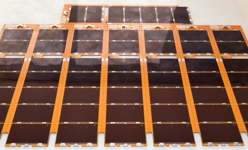
To implement this functionality, we've added a new software feature to the BM 2 -- a sleep mode. When the BM 2 is sleeping, all power to the rest of the spacecraft is disabled, and the BM 2 maintains an internal "sleeping clock." With the BM 2 sleeping at around 1.5mA, a mission life of around 400 days is possible. Sleep can be commanded with single-minute resolution, with a maximum sleep time of 120 days (7200 hours) via a single command. When in a deep sleep, the BM 2 will wake up every two hours for one minute, giving the flight software the opportunity to cancel the sleep if desired. The new BM 2 firmware is currently being tested, and is available to all BM 2s built on Rev F1 or later hardware. We're currently completing a build of 3U-size custom solar panels for a large US Gov't prime. These are an update to panels we have made in the past. We developed a test script that reduced test & verification time for each panel by roughly one hour, making technicians everywhere rejoice! These are PMDSAS 5th-generation solar panels with a polyimide substrate and Spectrolab(R) XTJ rectangular CICs.
I find that a lot of engineers do not understand the role of a Watchdog Timer (WDT) and how to use it properly. In this series I will cover various important aspects of WDTs as applied to embedded systems in general, and to nanosatellites in particular.
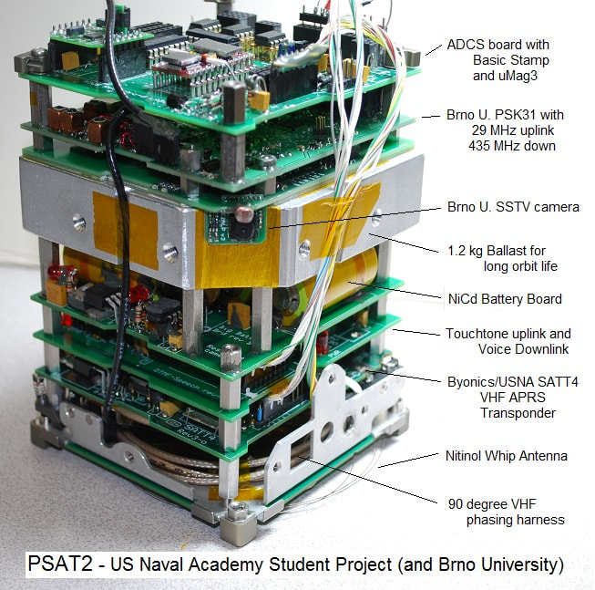
The purpose of a WDT is to help the system autonomously recover from a serious error. This recovery is usually in the form of a restart or reset, and after this restart or reset, the system will be in a well-defined initial (and, presumably rather safe and correct) state. Suppose, for example, that your system included a small piece of code that had not been tested particularly well. Sometime during normal operation, your application found itself in this little code snippet, and from external appearances, stopped working. In reality, this little snippet had an (unintended) infinite loop in it, and this prevented the application from operating normally. But you don't know that; all you know by observing your application is that it suddenly stopped working, it stopped responding to commands, etc. In a situation like this, all you can typically do is press the reset button (I hope you incorporated one in your design), watch the application restart, and then get to the bottom of this problem. Think of a WDT as a reset button that automatically restarts the application when and only when the application software/firmware goes "into the weeds." WDTs all share a basic behavior; namely, that the application must regularly communicate with the WDT within a certain window of time, or else the WDT will cause the application to restart. WDTs can be internal via software or external in the form of a standalone hardware WDT. When we say that we "kick" the WDT, we mean that we interact with the WDT to prevent it from restarting the application. How and when to kick your WDT is a subject unto itself, that we may cover at a later time. Suffice it to say that you must structure your software/firmware such that whenever your application stops working properly, the result is that the WDT is no longer being kicked, and the system will automatically restart, a short time later. In the example above, we're stuck in a loop (that presumably doesn't kick the WDT), and so by being stuck in that loop, the Timer part of the WDT expires (because the WDT is not being kicked), and therefore the WDT forces a system reset/restart. Let's examine the "a short time later" clause, above, and how it may apply to nanosatellites. On a typical nanosatellite, imagine a serious but recoverable software fault (say, one that inadvertently disables the nanosatellite's receivers). Whether the WDT forces a restart in 20ms or 2 minutes or 2 hours or 2 days is up to the designer, though the faster the reset/restart, the less time we'll spend waiting for the system to come back online and receive commands after this software fault. Some nanosatellite power systems have a feature whereby they will power-cycle the entire spacecraft if they don't receive a command or telemetry request within a specified period; this is eminently suited to solve this sort of problem, and is a nice example of a real-world WDT in action. These power systems ignore a system-wide -RESET signal; they neither respond to it, nor do they drive it. Instead, they cycle off and then on all power that is sourced to the other systems in the nanosatellite, and thereby force a system-wide software/firmware restart via Power-On Reset (POR). There are subtleties surrounding a signal like -RESET that we'll explore later in this series. Now imagine a software fault where a high-pressure propulsion valve gets stuck in the open position due to a software fault. In this case, the nanosatellite can quickly spin out of control and/or exhaust its supply of propellant, should the valve remain energized and open. Here, a WDT with a much faster kick rate (say, at 100Hz) is required to ensure that the valve never stays open for more than 10ms longer than it should. The takeaway here is that some software failures are perfectly well-served by WDTs with long periods, but others require a much faster system response, and hence a "faster" WDT. In the next installment, we'll explore how the WDT is connected to the rest of a typical nanosatellite. AEK There's a reason why we refer to our Chief Mechanical Engineer Adam Reif as "Close Tolerance Reif," or CTR. Pumpkin customers benefit from Adam's obsession with turning out a quality product at a good price. The U.S. Naval Academy's Bob Bruninga sent us a thank-you email yesterday, as USNA was completing the assembly of their PSAT2, which utilizes a COTS Pumpkin 1U structure: PUMPKIN ROCKS! After a three year design, leading to today and after finally (for the first time) snapping the top panel on our 1.5U CubeSat and having everything fit perfectly, I just had to stop in celebration and come over and send this Email. BRAVO ZULU! It just fits. Everything in the 1.5U frame just fit together perfectly. Especially since we have a 1.2kg central ballast (for longer orbit) and total 1.5U mass of 2.8 kg. The one mod I made was a small 0.1” notch at each of the corners of the side fame so that when it has slid down over the top of our full stack and the 1.2kg central mass (which is the precise dimensions of the walls so it can be screwed to the walls), that I can then use a small screwdriver at each corner post to get the side frame “started” when I go to remove it. Without those slots, the fit of the side sleeve to the bottom is so perfect that there is nothing to get in there and pry it loose. Attached is stack photo. Bob Bruninga, PE US Naval Academy Bob relates that PSAT2 is "Built by students for self training in radio art and only using Alumni GIFT funds." More info is available at http://aprs.org/psat2.html
Image courtesy of United States Naval Academy From the joint JPL-Pumpkin ISARA project that began in 2012, today the 3U ISARA spacecraft is on-orbit and undergoing initial trials. ISARA is equipped with a deployable 24-cell Pumpkin PMDSAS solar array that also has a Ka-band reflectarray antenna on its backside. The conductive pattern on the reflectarray side is analogous to a Fresnel lens for Ka-band wavelengths, implemented as discrete patches arranged in a particular pattern. Pumpkin worked with Dr. Richard Hodges and his group at JPL to develop a process whereby the JPL-designed reflectarray could be incorporated into Pumpkin's PMDSAS deployable solar panel technology and manufacturing, to yield flat and extremely stiff dual-purpose panels. Naturally, Pumpkin's space-grade hinges were used on these panels. In the images above, you can see the backside of the deployed Pumpkin 3-panel solar array + reflectarray. The metallic-color pieces between the panels are the Pumpkin hinges that enable the reflectarray to wrap around the ISARA structure when stowed. Solar power (from the solar cells on the opposite sides of these panels, not visible in these images) is routed from the central panel into the 3U bus at the hinge interface located at the base of the center panel. The smaller 4x4 array of patches on the opposite side of these fisheye-view images captured on orbit is the feed antenna for the reflectarray.
Dr. Hodges reported on January 16 that the Pumpkin solar array is functioning properly. The Aerospace Corporation is currently doing checkout of the various spacecraft bus components (e.g., Star Tracker and ACS). We wish them luck with this ground-breaking effort! On-orbit images courtesy of JPL / NASA. More information at https://www.jpl.nasa.gov/cubesat/missions/isara.php. The Australian government's Defense Science & Technology Group's Buccaneer Risk Mitigation Mission (BRMM) CubeSat launched on Saturday aboard the penultimate Delta II launch, from Vandenburg AFB. DST Group has been in contact with Buccaneer, successfully updated some critical configuration parameters, and will now "settle into a normal tempo of spacecraft operations."
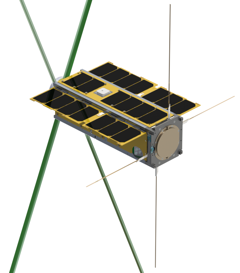
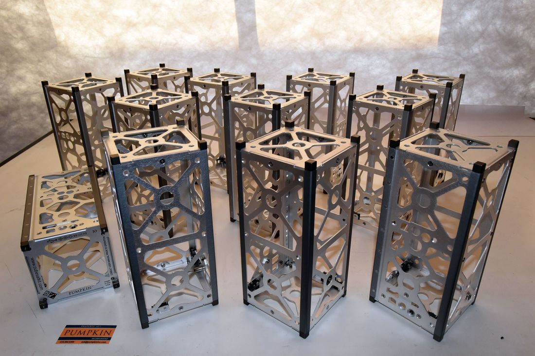
Buccaneer is a 3U MISC 3-class nanosatellite with full 3-axis attitude control and RF payload(s). Pumpkin developed the bus, structure, and deployable solar panels, and integrated the UHF, S-band and GPS antennas, Panel Release Mechanisms (PRMs), various bus sensors and other mission-specific components. As part of our typical fixed-firm price (FFP) nanosatellite offerings, this MISC 3 is highly customized for DST Group. Payload integration was verified virtually via CAD exchanges, and then physically in Australia, without any Pumpkin intervention. Pumpkin is registered with DDTC and can perform ITAR-affected work for entities outside of the USA, subject to license approval. We wish DST Group the best with their BRRM CubeSat, and hope to work with them again in the future. Twelve complete 2U CubeSat Kit skeletonized chassis are ready to ship. Each chassis consists of a dual-switch Baseplate Assembly, a 2U Chassis Walls, and a Cover Plate Assembly; all skeletonized. This is a repeat customer in the USA. We wish them luck with their future mission(s)!
|
Archives
April 2023
Categories |
Home |
About Us |
Store |
Salvo RTOS |
Contact
|
Copyright © 2015-2022

 RSS Feed